Choose self-tapping screws for plastic by matching the thread design to the resin, pilot hole and surrounding plastic, then checking head seating, thread engagement and tightening conditions on actual parts. Screw diameter alone cannot establish a suitable hole size or installation torque.
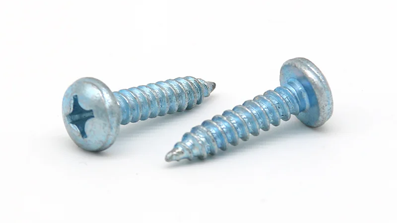
This guide concerns metal screws fastening into plastic components. These screws create their mating thread during installation, but the applications discussed here require a prepared hole, which may be molded into the part. HENGZUAN lists PVC, ABS and appliance plastic housings among the applications for its Phillips pan head self-tapping screw. Selecting that product for a particular housing still requires checking the connection: the same screw can behave differently when the resin grade, hole geometry or assembly process changes.
Which Plastic and Joint Conditions Are You Fastening?
Start with the actual plastic grade and the section of the part receiving the screw. A general description such as “ABS cover” leaves out information that affects thread formation and the strength of the surrounding material.
The screw may enter a thick wall, a molded boss or an existing threaded hole. A boss is the raised plastic feature surrounding a screw hole. Its available wall thickness and support matter because the screw loads the surrounding plastic as it forms and tightens the connection.
| Information to confirm |
Why it affects selection |
| Resin grade and reinforcement or filler |
Material behavior affects how the mating thread forms and how the joint responds to loading. |
| Hole and boss dimensions |
The plastic around the hole must accommodate thread formation without losing the required support. |
| Upper component and its clearance hole |
The screw must allow the components to come together and seat as intended. |
| Service and maintenance requirements |
Heat, sustained loading, chemical exposure and disassembly may require checks beyond initial installation. |
For example, changing the resin in an otherwise unchanged housing is a reason to review the fastening conditions. An old tool setting and an unchanged screw designation do not establish that the revised part will assemble in the same way.
Which Thread Design Fits the Plastic Application?
Compare the thread profile as well as its outside diameter. Pitch, flank geometry and core diameter influence the space available for displaced plastic and the loading applied to the hole wall. Two screws with the same nominal diameter can therefore require different hole designs.
Thread-forming screws displace material to create a mating thread. Thread-cutting designs remove material through a cutting feature. A pointed tip alone does not identify a thread-cutting screw, and the two approaches should not share a hole recommendation simply because their diameters match.
Some screws designed specifically for thermoplastics use thread geometry intended to reduce radial loading while maintaining engagement. That can be relevant where a thin boss, high insertion resistance or a narrow tightening margin makes a conventional tapping thread difficult to use. The suitability of the screw and boss still needs checking together.
HENGZUAN’s Phillips pan head self-tapping screws are listed as carbon steel products under the GB/T845-1985 designation, with PVC and ABS among their stated applications. Use the product specification and the actual housing drawing to check the diameter, length and thread geometry for the intended resin and boss design.
If a candidate screw produces excessive insertion resistance or boss cracking, examine the thread and hole combination before increasing torque. A different thread design may help, but it should be assessed against the same resin, joint geometry and assembly requirements.
How Should the Pilot Hole and Screw Boss Be Designed?
Pilot Hole Diameter and Tolerance
A pilot hole for screws in plastic must leave material for the thread to engage while allowing the screw to enter without excessive loading. A smaller hole is not automatically a stronger choice. It can raise insertion resistance and expand the surrounding plastic; an oversized hole can leave insufficient engagement.
Use a recommendation that applies to the particular screw geometry and resin, then verify it on the component. Hole ratios published for a specialist screw should not be transferred to an unrelated tapping screw.
Specify the tolerance as well as the nominal diameter. A trial using one conveniently sized hole can miss difficulties at either end of the production range. For a molded hole, check its taper and the dimensions along the engagement depth. Measuring only the opening may not describe the section in which the screw forms its thread.
Boss Walls, Hole Entry and Blind-Hole Depth
Plastic screw boss design includes the material around the hole, the entry and the available depth. Increasing interference by reducing the pilot hole also changes the load on the boss wall. Where that wall is thin or poorly supported, the change may cause cracking instead of improving the joint.
An entry relief can help manage stress near the opening in an appropriately designed connection. Its dimensions belong to the screw and component design; they are not a universal machining instruction.
In a blind hole, leave room for the screw point beyond the intended full-thread engagement. Confirm this clearance with the components in their seated position. A screw that reaches the bottom before the head seats can produce a high torque reading while leaving the assembly loose.
Also distinguish the receiving hole from the upper component’s clearance hole. Where a cover must be pulled against a lower boss, unintended thread engagement in the cover can interfere with that movement.
How Do Head Seating and Screw Length Affect the Joint?
The screw head needs a suitable bearing surface, and the connection needs usable thread engagement. Check both in the assembled position.
A pan head normally bears against a supporting seat beneath the head. It should not be driven into an unsuitable plastic surface to create a flush appearance. Where the head sits within a recess, confirm the recess geometry, the remaining support and access for the driver.
For a HENGZUAN pan head screw, review the actual head dimensions against the housing seat. If the head contacts an edge, tilts or visibly deforms the plastic before the components close, increasing torque does not correct the geometric mismatch.
Screw length must account for the upper component and the portion entering the receiving plastic. The tapered point does not provide the same full-profile engagement as the threaded section behind it. Excess length can instead make the tip bottom out before the joint closes.
A longer screw may provide additional engagement when sufficient boss depth is available. Confirm the resulting insertion behavior and bottom clearance, rather than using added length to compensate for an unsuitable hole or damaged thread.
How Can You Set Tightening Torque Without Stripping the Plastic?
Insertion, Tightening and Stripping Torque
Insertion torque is the maximum torque encountered while the screw enters, before the head reaches its seat. Tightening torque is applied to complete the connection after seating. Stripping torque marks failure of the plastic thread. The joint needs enough separation between normal assembly demands and failure to accommodate variation in parts and equipment.
The boss, head seating area or screw can fail before the plastic thread strips. A usable setting must allow for variation before the first relevant failure, including cracking, head pull-through or screw damage where those are possible.
Torque also depends on friction at the threads and beneath the head. Changing the finish, adding a lubricant or changing the component surface can alter the relationship between measured torque and clamping. A torque value from another screw and housing combination is therefore insufficient evidence for the present joint.
Trial Assembly on Actual Parts
Use representative components and a controlled assembly process to establish the setting. A practical sequence is:
- Confirm the components. Record the screw, resin grade, hole and boss dimensions, seating arrangement and surface condition.
- Observe insertion and seating. Check that the screw enters correctly and the parts close before the tool stops. Torque and rotation records, where available, can help distinguish these stages.
- Establish failure behavior on test pieces. Determine whether excess tightening strips the plastic thread, cracks the boss, damages the seat or causes another failure. Do not use specimens from destructive tests in production assemblies.
- Check a working setting across representative variation. Include the relevant hole tolerances and component conditions instead of relying on one successful assembly.
- Record the validated process. Keep the tool, speed, cut-off method and screw condition consistent with the trial, and review changes before using them in production.
The following observations help direct investigation; each can have more than one cause.
| Assembly observation |
What to check first |
| Boss cracks while the screw enters |
Hole size and shape, surrounding wall, thread geometry and alignment. |
| Screw stops while a gap remains |
Blind-hole depth, unintended engagement in the upper part and head seating. |
| Screw keeps turning without tightening the joint |
Plastic thread damage, available engagement and the condition beneath the head. |
| Identical tool settings give inconsistent results |
Hole variation, material condition, screw surface condition and tool performance. |
If the margin between successful seating and damage is too narrow, revisit the connection design. Selecting a higher tool setting cannot create a stable assembly window that the joint itself lacks.
What Changes with Repeated Assembly and Service Conditions?
Repeated assembly needs its own evaluation. During initial installation, the screw creates the mating thread. On reassembly, it should follow that existing thread without cutting or forming a competing path. Start carefully and check for damaged threads or a screw that no longer seats and holds as intended.
There is no universal reuse count for self-tapping screws in plastic. Where a housing will be opened for maintenance, test the required disassembly and reassembly sequence on the intended components. Include the assembly method that maintenance personnel will actually use.
Service conditions can also expose problems that are absent immediately after tightening. For parts under sustained loading or temperature changes, assess whether the connection retains the required clamping and function over the intended conditions. A torque check performed by turning the screw further does not directly measure the remaining clamp load.
Check chemical compatibility as well. Lubricants, cleaning agents and manufacturing residues can affect some plastics and contribute to stress cracking, which may appear after assembly. Adding an unverified lubricant to reduce insertion resistance changes the conditions being evaluated.
Selecting self-tapping screws for plastic means confirming the screw, material, hole, seat and assembly process as one connection. To discuss your plastic fastening requirements with HENGZUAN, provide the resin grade, a drawing of the hole and boss, the intended screw dimensions, assembly and maintenance requirements, and quantity.